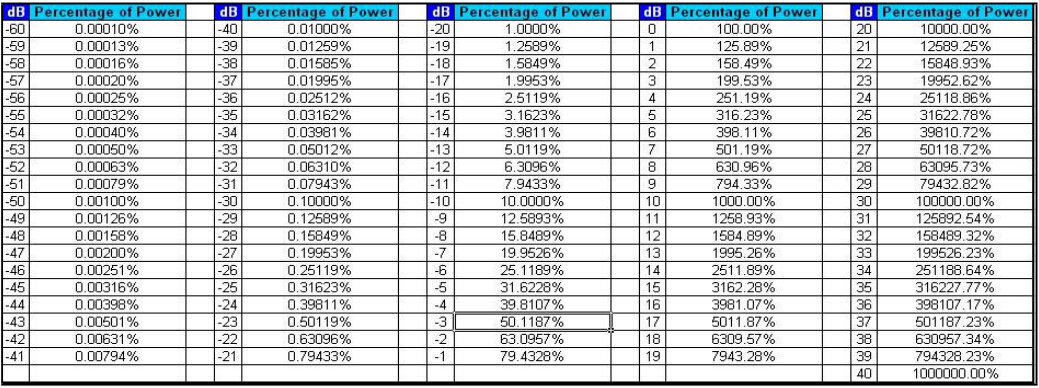
Fiber Optic Cable Coupler Loss Chart

Fiber Optic Splitter Box At Best Price In China Baymro Technology Buy Fiber Optic Splitter Box From China Import Fiber Op Splitters Fibre Optics Fiber Optic
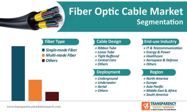
Fiber Optic Cable Market To Reach Valuation Of Us 15 Bn By 2030
Fiber Optic Couplers Selection Guide Engineering360
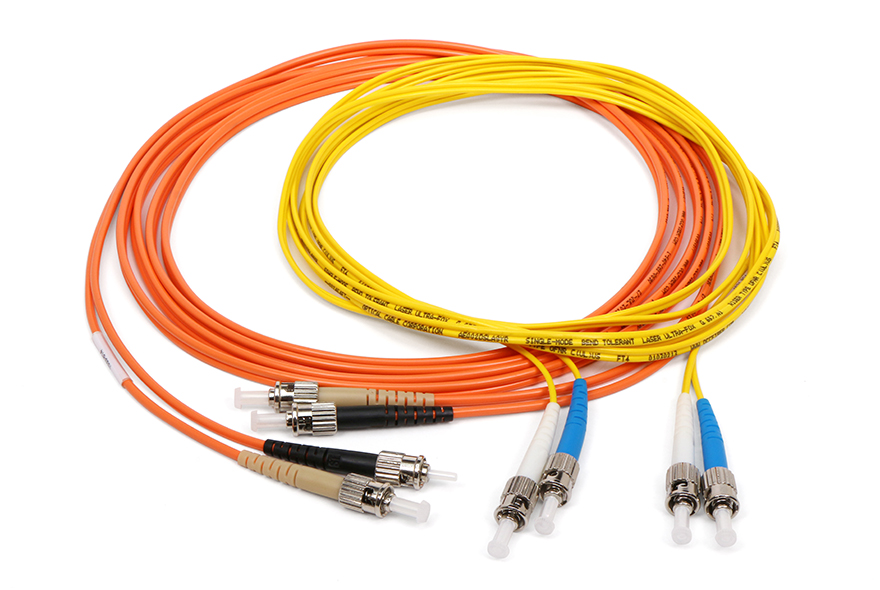
Fiber Optic Jumpers Optical Cable Corporation

12 Fiber Mtp Mpo To Lc Fiber Optic Fanout Cable Multimode Om3 Plenum Cables Plus Usa
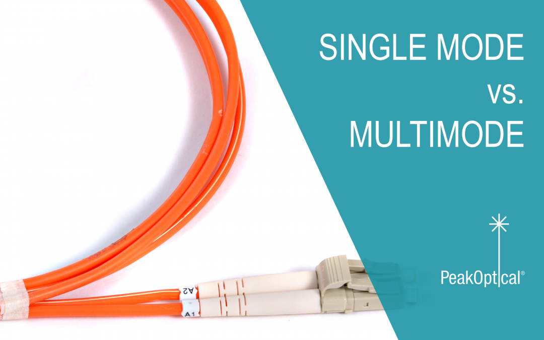
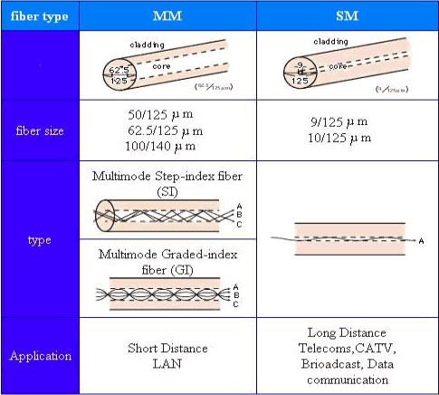
Single Mode Vs Multimode Fiber Optic Cables Peakoptical A S

Signal loss in multimode and single mode fiber optic cable attenuation and dispersion in fiber optic cable.
Fiber optic cable coupler loss chart. Optical splitter loss ratio 1 n. Insertion loss for a connector or splice is the difference in power that you see when you insert the device into the system. Real world fiber optic splitters show uniform performance across the whole spectrum of interest from 1260 to 1600 nm. 1 n fiber optic splitter loss ratio chart are given bellow.
For example take a length of fiber and measure the optical power through the fiber. Optical coupler is an optical device that combines or splits power from optical fibers. Now cut the fiber in half terminate the fibers and connect. The estimate called a loss budget is calculated using typical component losses for each part of the cable plant.
Advantages are the low loss easy coupling with the optical fiber transmission line and no polarization dependent loss. Note the reading p1. Star couplers with up to 32 ports have been possible using fused tapered fiber 3 db couplers. Power budgets and loss budgets the terms power budget and loss budget are often confused the power budget refers to the amount of fiber optic cable plant loss that a datalink transmitter to receiver can tolerate in order to operate properly.
Sometimes the power budget has both a minimum and maximum value which means it needs at least a minimum value of loss so that it does not overload.
Understanding Link Budget And Link Loss In Fiber Optic Network
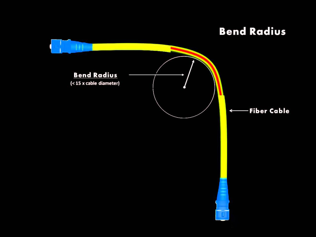
Fiber Bend Radius What S It How It Affects Fiber Cable Installation

Fiber Optic Communications For The Premises Environment By Dr Kenneth S Schneider Phd Chapter 2

Duplex Fiber Coupler St St Singlemode And Multimode Fiber Optic Cable Fiber Duplex

8 Fiber Mtp Mpo Qsfp Qsfp Fiber Optic Cable Multimode Om4 Plenum

Amazon Com Karono Mpo Mtp Breakout Cable Mpo Mtp To 8 X Lc 4 Duplex 40gbe Qsfp 40gbase Sr4 Om3 Fanout Fiber Optic Cable Aqua 3m 10ft Home Audio Theater

How To Repair Fiber Optic Cable Youtube
What Is The Difference Between Multimode And Singlemode Fibre Optic Cable Universal Networks

Wrapping Tube Wtc Cable With Spiderweb Ribbon

Plc Splitter And Download The Loss Chart Of Plc Splitter Splitters Fiber Optic Power

Prysmian And Draka Cable S670t Armored And Sheathed Marine Fiber Optic

Fiber Optic Cable An Overview Sciencedirect Topics

Sc Apc Fiber Adapter Sc Duplex Multi Mode Single Mode Pbt Material Adapter Low Insertion Loss Adapter Fiber Optic Apc

